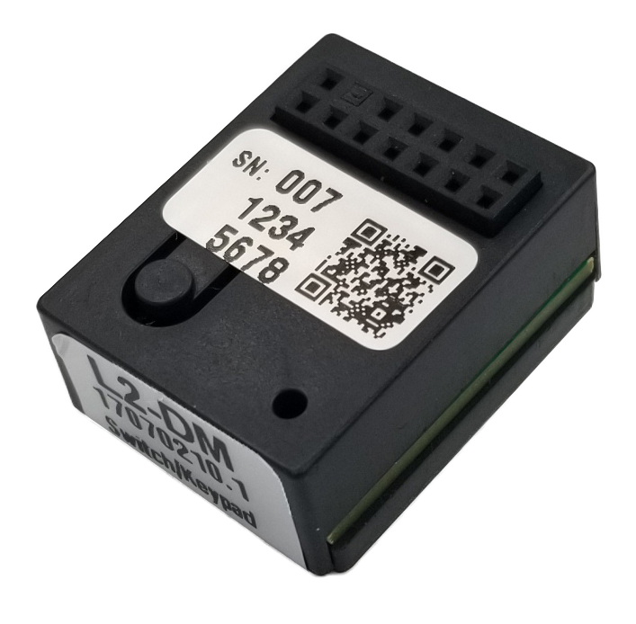
L2-DM
Switch/Keypad Input and 1 Zone PDM controller, Dimming, Communicating
The Dimming Module controls a Zone of lights by reading input signals from attached switches or keypads connected to the PDM Port, and creates a Channel signal on the PDM. Up to 128 driver modules can listen to the Channel creating a group, or Zone, of lights. The L2-DM can be “stacked” underneath any driver so both switch inputs and lights can be attached to the same PDM Port. Only one L2-DM is allowed per Channel to create the PWM Channel signal. The L2-DM also sends 12VDC Accessory Power from the Accessory Power Regulator (L2-APR) to the RJ45 Port through a protection fuse. An L2-APR is required to power the microcontroller in the L2-DM. Up to 16 L2-DM are powered by the L2-APR in the middle of the PDM. L2-DM can receive commands and transmit their output status over the PDM communication bus to interface to third party control systems and the L2-EGW Ethernet Gateway. Solving many more roles than just a dimmer for lighting, eleven modes of operation allow the L2-DM to read on/off, momentary, top/bottom switches, motion sensing, occupancy sensing, exhaust fan controls, ceiling fan controls, doorbells, and 1 to 8 button keypads. No software or gateway is required for most configuration steps, even setting basic lighting scenes thanks to 1 button macros. Advanced settings can be accessed using the L2-EGW.
L2-DM SET button and indicator LED operation:
The green LED indicator on the front face of the L2-DM indicates one of 11 Mode states (0..10) by flashing the Mode number, then a small pause, then repeating the cycle. Wait for the pause and count the number of flashes to obtain the mode.
Press the SET button on the face of the L2-DM to increment the Mode and cycle from 0 (solid LED indicator) to 10 flashes (Mode 10). Pressing the SET button when you see 10 flashes will return to Mode 0 (LED on solid).
MODE | MODE NAME | PORT DEVICES | DESCRIPTION |
0 | Remote Only | n/a | Ignores all switch inputs from the Port. Only responds to serial data commands via the Comm Bus. |
1 | Normally Open Switch | N/O door switch, Relay | Sets zone to OFF when the switch input is shorted. Sets zone to 100% when the switch input is open. Used for toggle switches or automatic door pushbuttons. |
2 | Normally Closed Switch | N/C door switch, Relay | Opposite action of Mode 1. Turns on the zone when the input is an open circuit. |
3 | Button Toggle ON/OFF | Buttons, L3-KP1, L3-TP1 | Toggles output between OFF and 100% each time the momentary button is released. Top and Bottom buttons do the same function when using an L3-KP1. |
4 | Top/Bottom Switch w/ Restore Level | L3-WK1 | Two momentary buttons: Tap the UP button to set output to Restore Level. Tap UP button again to set output to 100%. Tap the DOWN button to turn OFF the zone. |
(5) | Top/Bottom Switch w/ Restore Level and Dim/Raise | L3-WK1 | Tap the UP button to set output to Restore Level. Tap the UP button again to set output to 100%. Tap the DOWN button to set output to OFF. Hold the UP button to raise output to 100%. Hold the DOWN button to lower output to 1%. Default mode. |
6 | Button Toggle ON/OFF w/ Dim/Raise | L3-KP1, L3-TP1 | Tap to cycle between A)Restore Level, B)100%, and C)OFF. Hold when output is below 50% to raise output level. Stops at 100%. Hold when above 50% to dim output. Stops at 1%. Alternate mode is selectable via Gateway commands. Top and Bottom buttons on an L3-WK-D respond the same to the tap feature. |
7 | Silent Follower | n/a | Ignores all switch inputs and responds to level replies from DM messages with the same ID. This mode does not send a reply message to a level change. |
8 | Keypad, Touchpad | L3-KP*, L3-TP* | Performs one of 4 functions responding to one of 8 keypad buttons being pressed. Any of the buttons can A)Request a Scene, B)Toggle a Zone ID, C)Toggle a Scene on/off, D)Raise the last zone button pressed, or E)Dim the last zone button pressed. Buttons 1..8 can be spread across multiple attached keypads attached to the L2-DM in groups of 4. |
Manually set and view the ID number:
Typically the ID #s will be assigned by the L2-EGW Gateway. To manually assign an ID # of an L2-DM, Hold the SET button for 3 seconds and release. Then tap the SET button the number of times of the ID. The green LED will flash each time you press the SET button. Wait 5 seconds without pressing the button and the LED will remain solid for 2 seconds indicating the ID has been stored. To check the ID, hold the SET button for 3 seconds, release, and count the LED flashes.
| POWER & CONNECTIONS | ||
| Power consumed | 0.2 W (Requires L2-APR on the same L2-PDM) | |
| Top connector | Female 14 pin, 1 alignment pin (plugged) | |
| Bottom connector | Male 14 pin, 1 alignment pin (clipped) | |
| PDM voltage | 12-65VDC (pass through) | |
| Port voltage maximum | 65VDC (pass through) | |
| Current maximum | 1.5A (pass through) | |
| Port current maximum | 1.25A | |
| Accessory 12V protection | 1.2A non-resettable fuse | |
| RS485 CONTROL BUS | ||
| Communication speed | 38,400 bps | |
| Control protocol | Published dimming module protocol | |
| ZONE CHANNEL OUTPUT | ||
| Control channel signal type | 0-5VDC, PWM Broadcast | |
| Maximum drivers controlled | 128 | |
| PORT SWITCH INPUT | ||
| Switch types | 1 button momentary, Top/Bottom momentary 2 button, 1-8 button keypad, ON/OFF switch, Motion detector, Occupancy detector, Ambient light threshold sensor, Sensor relay (leaks, temperature, etc) | |
| PHYSICAL/ENVIRONMENTAL | ||
| Dimensions | 1 x 1.25 x 1.1in (25 x 34 x 30mm) | |
| Operating temperature | +32°F to +122°F (0°C to +50°C) | |
| Operating humidity | 5% to 95% Non-condensing | |
| Rating | Dry Rated | |
| Environmental | RoHS | |
| Safety certifications | FCC, CE | |
| WARRANTY | ||
| Duration | 5 Years |